6 DOF Robot Arm Arduino Programmable (Fully Assembled)
Order before 12.00PM
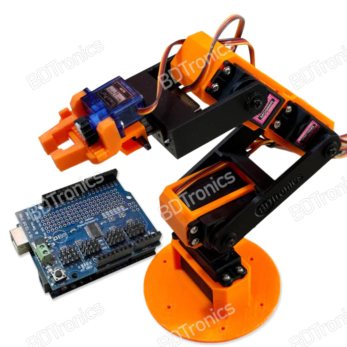
BDTronics 6-DOF Robotics Arm Kit is an 3D printed Arduino-Compatible learning kit is an essential tool for electronics hobbyists, robotics enthusiasts, and students eager to explore Arduino programming, kinematics, and mechanical principles. This kit offers a hands-on experience in building and programming a versatile robotic arm, ideal for various educational and hobbyist projects. Custom 3D printed parts ensures every part is replaceable and available if broken or damaged.

Arduino Programmable:
This robot arm is fully compatible with Arduino and can be programmed with Arduino IDE. You can create custom moves using the basic programming skills. No special library or tool is necessary.
PC Software:
Take full control of your 6-DOF robotic arm with BDTronics’ intuitive controller software. Featuring real-time servo adjustment, motion sequence programming, and precise delay handling, this Windows-based application is perfect for automation, education, and prototyping. Easily connect via USB, create complex motion sequences with drag-and-drop simplicity, and bring your robotic projects to life.
Features:
-
Arduino-Compatible: The included Arduino UNO microcontroller board is perfect for all experience levels, allowing easy programming through the Arduino IDE, which supports a wide range of coding languages and libraries.
-
Precise Servo Control: The arm is powered by 3 MG996 metal gear servos, providing the strength and durability needed for complex tasks. These servos control the base, shoulder, and elbow joints. Additionally, two SG90 servos are dedicated to the grip's rotation and the gripping mechanism, ensuring precise and responsive control.
- Base: 61.50mm
- Shoulder: 78.00mm
- Upper Arm: 78.50mm
- Lower Arm: 54.50mm
- Wrist: 43.00mm
- Max Grip: 11.00mm
- Ergonomic Mechanical Design: The arm's structure is carefully designed for optimal performance:
- This design allows a wide range of motion and the ability to attach any lightweight mechanical grip or tool for specific tasks.
-
Comprehensive Learning Tool: This kit is ideal for learning both Arduino programming and essential robotics concepts such as kinematics and mechanical principles. It's an excellent educational resource for classrooms, workshops, and personal projects.
- Safety Notice: To prevent damage to your computer's USB port, always use an external 5V power supply or battery to power the servos or servo shield.
Applications:
This kit can be utilized in various applications, including:
- Educational Projects: A perfect resource for students and educators exploring robotics and programming.
- Prototyping: Ideal for engineers and hobbyists seeking to prototype robotic systems.
- Home Automation: Suitable for integration into home automation projects for tasks such as pick-and-place operations.
- STEM Learning: A hands-on tool for learning STEM (Science, Technology, Engineering, and Mathematics) concepts in an interactive manner.
Package Includes:
- Robotic Arm Kit
- 3 x MG996 Full Metal High Quality Servo
- 2 x SG90 Servo
- 1 x Arduino Compatible Robot Controller
- 1 x Instruction Manual
- 1 x USB Cable
Wiring diagram with the Arduino servo shield:
- PWM Channel 0: Base servo (Horizontal rotation)
- PWM Channel 1: Shoulder servo
- PWM Channel 2: Upper arm servo
- PWM Channel 3: Lower Arm servo
- PWM Channel 4: Wrist Servo
- PWM Channel 5: Grip Servo

Sample Code:
Follow the steps below to upload the following sample code.
1) At first, make sure disconnect the power line and dismount the servo shield from your Arduino UNO board.
2) Open Arduino IDE, copy and paste the following code. Save the project.
3) Connect your Arduino UNO to your computer via USB and upload the project.
4) After successfully uploading the code, disconnect the USB.
5) Mount the Servo Shield on top of your Arduino UNO and place the robot arm on top of a flat surface/ table. Make sure, it has enough space and doesn't collide with anything nearby.
6) Connect all of the servo connectors to their respective PWM channel in the servo shield. Follow the instruction above for any guidance.
7) You must provide 5V to the Arduino Servo Shield from a separate power supply. Never use your computer USB port to power the servo.
8) At this moment, the robot arm won't be active yet. Now, you must connect your Arduino via USB to your computer or from a USB power bank.
/*
  6DOF Robotic Arm Control with PCA9685 and Arduino UNO

  This code controls a 6DOF robotic arm using MG996 and SG90 servos,
  managed by a PCA9685 servo driver connected to an Arduino UNO.
  The arm performs pick-and-place operations with smooth movements
  to prevent servo wear.

  BDTronics 2024. All rights reserved.
*/

#include <Wire.h>
#include <Adafruit_PWMServoDriver.h>


#define SERVOMIN 150  // Minimum pulse length count (out of 4096)
#define SERVOMAX 650  // Maximum pulse length count (out of 4096)

// Servo channel assignments
#define BASE_SERVO 0
#define SHOULDER_SERVO 1
#define UPPER_ARM_SERVO 2
#define LOWER_ARM_SERVO 3
#define WRIST_SERVO 4
#define GRIPPER_SERVO 5

#define CALIB_SERVO 15

#define GRIPPER_MAX 20
#define GRIPPER_MIN 160
#define STEP_DELAY 40  // Delay in milliseconds between steps
#define STEP_SIZE 1    // Step size in degrees

#define SERVO_CALIB_PIN 13

// Track the current position of each servo
int initalPosition[6] = { 90, 45, 90, 135, 90, 20 };   // Initial positions
int currentPosition[6] = { 90, 45, 90, 135, 90, 20 };  // Initial positions


Adafruit_PWMServoDriver pwm = Adafruit_PWMServoDriver();


void setup() {
  pinMode(SERVO_CALIB_PIN, INPUT_PULLUP);

  pwm.begin();
  pwm.setPWMFreq(60);  // Analog servos run at ~60 Hz

  //Servo calibration
  if (digitalRead(SERVO_CALIB_PIN) == LOW) {
    while (true) {
      pwm.setPWM(BASE_SERVO, 0, angleToPulse(90));
      pwm.setPWM(SHOULDER_SERVO, 0, angleToPulse(90));
      pwm.setPWM(UPPER_ARM_SERVO, 0, angleToPulse(90));
      pwm.setPWM(LOWER_ARM_SERVO, 0, angleToPulse(90));
      pwm.setPWM(WRIST_SERVO, 0, angleToPulse(90));
      pwm.setPWM(GRIPPER_SERVO, 0, angleToPulse(90));
      pwm.setPWM(CALIB_SERVO, 0, angleToPulse(90));
    }
  }

  // Initialize servos to the starting position
  moveToStartPosition();
}

void loop() {
  // Example sequence: Pick an object and place it somewhere else

  // Move to pick position
  openGripper();
  moveToPickPosition();
  delay(1000);

  // Close the gripper to pick the object
  holdGripper();
  delay(1000);

  // Move to hold position
  moveToHoldPosition();
  delay(1000);

  //Show the object
  moveServo(WRIST_SERVO, 45);   // Wrist aligned
  moveServo(WRIST_SERVO, 135);  // Wrist aligned
  moveServo(WRIST_SERVO, 90);   // Wrist aligned

  // Move to place position
  moveToPlacePosition();
  delay(1000);

  // Release the object and move away from it
  openGripper();
  delay(500);
  moveServo(SHOULDER_SERVO, 45);    // Upper arm adjusted
  moveServo(UPPER_ARM_SERVO, 100);  // Shoulder adjusted
  delay(1000);

  //Move to return pickup position
  moveToPlacePosition();
  delay(500);

  //Pickup the object again
  holdGripper();
  delay(1000);

  // Move to hold position
  moveToHoldPosition();
  delay(1000);

  // Return to start position
  moveToStartPosition();
  delay(1000);

  //Place the object where it was first picked from
  moveToPickPosition();
  delay(500);
  openGripper();
  delay(1000);

  // Move away from it
  moveServo(SHOULDER_SERVO, 45);    // Upper arm adjusted
  moveServo(UPPER_ARM_SERVO, 100);  // Shoulder adjusted
  delay(1000);
  moveToStartPosition();
}

void moveToStartPosition() {
  moveServo(BASE_SERVO, initalPosition[0]);       // Base centered
  moveServo(SHOULDER_SERVO, initalPosition[1]);   // Shoulder neutral
  moveServo(UPPER_ARM_SERVO, initalPosition[2]);  // Upper arm neutral
  moveServo(LOWER_ARM_SERVO, initalPosition[3]);  // Lower arm neutral
  moveServo(WRIST_SERVO, initalPosition[4]);      // Wrist neutral
}

void moveToPickPosition() {
  moveServo(BASE_SERVO, 45);        // Base rotated
  moveServo(SHOULDER_SERVO, 105);   // Shoulder raised
  moveServo(UPPER_ARM_SERVO, 80);   // Upper arm lowered
  moveServo(LOWER_ARM_SERVO, 140);  // Lower arm raised
}

void moveToHoldPosition() {
  moveServo(SHOULDER_SERVO, 45);    // Upper arm adjusted
  moveServo(BASE_SERVO, 135);       // Base rotated to place position
  moveServo(UPPER_ARM_SERVO, 100);  // Shoulder adjusted
}

void moveToPlacePosition() {
  moveServo(SHOULDER_SERVO, 105);   // Shoulder raised
  moveServo(UPPER_ARM_SERVO, 80);   // Upper arm lowered
  moveServo(LOWER_ARM_SERVO, 140);  // Lower arm raised
}


void holdGripper() {
  moveServo(GRIPPER_SERVO, 80);  // Gripper open
  //pwm.setPWM(GRIPPER_SERVO, 0, angleToPulse(80));
}

void closeGripper() {
  moveServo(GRIPPER_SERVO, 160);  // Gripper open
  //pwm.setPWM(GRIPPER_SERVO, 0, angleToPulse(160));
}

void openGripper() {
  moveServo(GRIPPER_SERVO, 20);  // Gripper open
  //pwm.setPWM(GRIPPER_SERVO, 0, angleToPulse(20));
}

void moveServo(int servo, int targetAngle) {
  int currentAngle = currentPosition[servo];
  int step = (currentAngle < targetAngle) ? STEP_SIZE : -STEP_SIZE;

  for (int angle = currentAngle; angle != targetAngle; angle += step) {
    pwm.setPWM(servo, 0, angleToPulse(angle));
    delay(STEP_DELAY);
  }

  pwm.setPWM(servo, 0, angleToPulse(targetAngle));  // Ensure final position
  currentPosition[servo] = targetAngle;             // Update current position
}

int angleToPulse(int angle) {
  int pulse = map(angle, 0, 180, SERVOMIN, SERVOMAX);
  return pulse;
}
Lesson for the advanced user
Transform the above code with kinematics calculations. To integrate kinematic transformations for your 6DOF robotic arm into the given code, you'll need to incorporate forward and inverse kinematics calculations. These transformations will enable you to compute the desired positions and angles of the servos to achieve specific end-effector positions.
Here’s an overview of how to modify the code to include basic kinematics:
-
Define DH Parameters: You'll need to define the Denavit-Hartenberg (DH) parameters for your robotic arm, which include link lengths, link twists, and joint angles. These parameters will help you in calculating the forward and inverse kinematics.
-
Implement Forward Kinematics: Forward kinematics will use the DH parameters to compute the position and orientation of the end-effector given the joint angles.
-
Implement Inverse Kinematics: Inverse kinematics will compute the required joint angles to achieve a desired end-effector position.
Here's an example of how to start implementing these steps in your code:
Step 1: Define DH Parameters
#define L1 10  // Length of link 1
#define L2 10  // Length of link 2
#define L3 10  // Length of link 3
#define L4 10  // Length of link 4

// DH parameters: [a, alpha, d, theta]
float dhParams[4][4] = {
  {L1, 0, 0, 0},
  {L2, 0, 0, 0},
  {L3, 0, 0, 0},
  {L4, 0, 0, 0}
};
Step 2: Implement Forward Kinematics
#include <math.h>

// Calculate forward kinematics
void forwardKinematics(float jointAngles[], float &x, float &y, float &z) {
  float a1 = dhParams[0][0];
  float a2 = dhParams[1][0];
  float a3 = dhParams[2][0];
  float a4 = dhParams[3][0];

  // Calculate end-effector position (x, y, z)
  x = a1 * cos(jointAngles[0]) + a2 * cos(jointAngles[0] + jointAngles[1]) +
      a3 * cos(jointAngles[0] + jointAngles[1] + jointAngles[2]) +
      a4 * cos(jointAngles[0] + jointAngles[1] + jointAngles[2] + jointAngles[3]);

  y = a1 * sin(jointAngles[0]) + a2 * sin(jointAngles[0] + jointAngles[1]) +
      a3 * sin(jointAngles[0] + jointAngles[1] + jointAngles[2]) +
      a4 * sin(jointAngles[0] + jointAngles[1] + jointAngles[2] + jointAngles[3]);

  z = 0;  // Assuming a 2D plane for simplicity; adjust for 3D if needed
}
Step 3: Implement Inverse Kinematics
Inverse kinematics can be complex and depends heavily on the specific structure of your robotic arm. Here’s a simplified example:
// Calculate inverse kinematics
void inverseKinematics(float x, float y, float &jointAngles[]) {
  float a1 = dhParams[0][0];
  float a2 = dhParams[1][0];
  float a3 = dhParams[2][0];
  float a4 = dhParams[3][0];

  // Solve for joint angles (simplified)
  jointAngles[0] = atan2(y, x); // Base angle

  float r = sqrt(x * x + y * y);
  jointAngles[1] = acos((r - a1) / a2); // Shoulder angle
  jointAngles[2] = acos((r - a1 - a2) / a3); // Elbow angle
  jointAngles[3] = 0; // Wrist angle
}
Update Your Servo Control Code
Replace the placeholder angles in your moveToPickPosition(), moveToHoldPosition(), and moveToPlacePosition() functions with the computed angles from your inverse kinematics calculations.
Example Integration
void moveToPickPosition() {
  float x = 10; // Example x position
  float y = 10; // Example y position

  float jointAngles[4];
  inverseKinematics(x, y, jointAngles);

  moveServo(BASE_SERVO, jointAngles[0]);
  moveServo(SHOULDER_SERVO, jointAngles[1]);
  moveServo(UPPER_ARM_SERVO, jointAngles[2]);
  moveServo(LOWER_ARM_SERVO, jointAngles[3]);
}
Note that this is just a hint for the implementation on your own. For a real robotic arm, you’d need to adjust the calculations based on your specific DH parameters and the arm’s geometry. If you have more complex kinematics, you might need to use a more sophisticated solver or library.
Recently viewed products
You might also be interested in...
Customers who bought this also bought...
General Questions
-
What is the latest price of the 6 DOF Robot Arm Arduino Programmable (Fully Assembled) in Bangladesh?
The latest price of 6 DOF Robot Arm Arduino Programmable (Fully Assembled) in Bangladesh is Special Price BDT 8,450.00 Regular Price BDT 9,500.00 . You can buy the 6 DOF Robot Arm Arduino Programmable (Fully Assembled) at the best price on BDTronics.com or contact us via phone.
-
Where to buy 6 DOF Robot Arm Arduino Programmable (Fully Assembled) in Bangladesh?
You can buy 6 DOF Robot Arm Arduino Programmable (Fully Assembled) online by ordering on BDTronics.com or directly collect by visiting our store in person. BDTronics is a trusted provider of high-quality electronics, 3D printers, solar systems, and robotics parts. We offer fast shipping across the country via courier service.
-
What are the delivery options of 6 DOF Robot Arm Arduino Programmable (Fully Assembled) in Bangladesh?
We provide home delivery service all over Bangladesh. We support Cash on Delivery, Online Bank Transfer, bKash and Credit Card (Visa/ MasterCard/ Amex) payment solutions. The delivery time usually takes 1-2 days inside Dhaka and 2-4 days outside Dhaka.