Infrared Obstacle Avoidance Sensor & 5 Channel Tracking IR Infrared Sensor
Order before 12.00PM
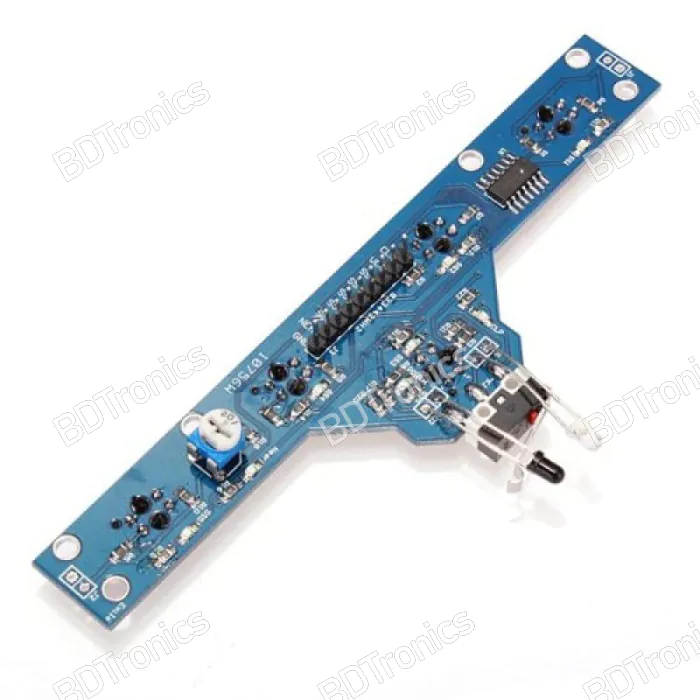
The BFD-1000 5 Channel Infrared Tracking Sensor Module is an advanced line-tracking and obstacle-avoidance sensor designed for smart cars, Arduino robots, and line follower robots. This module uses five high-precision infrared sensors to detect color contrasts such as black and white surfaces, allowing robots to follow lines accurately and make precise turns. It is ideal for robotics enthusiasts, automation learners, and developers building autonomous navigation systems.
Features:
-
Model: BFD-1000
-
Function: Line tracking and obstacle detection for robotic applications
-
Channels: 5 high-quality infrared sensors for precise path recognition
-
Working Principle: Infrared reflection detection between dark and light surfaces
-
Sensitivity: Adjustable sensitivity for various surface materials and lighting conditions
-
Output: 5 independent digital outputs, each representing one sensor’s detection status
-
Compatibility: Works perfectly with Arduino, Raspberry Pi, ESP32, and other microcontrollers
-
Mounting: Pre-drilled holes for stable installation on robotic chassis
-
Application: Line following, edge detection, obstacle avoidance, maze-solving robots
Specifications:
-
Operating Voltage: 3.3V – 5V DC
-
Output Type: Digital (High/Low detection)
-
Number of Sensors: 5 infrared sensors
-
Detection Distance: 1cm – 2cm (adjustable via onboard potentiometer)
-
Infrared Wavelength: 940nm
-
Response Time: Fast and accurate for real-time applications
-
Board Size: 76mm x 20mm
-
Weight: Approximately 15g
-
Interface Pins:
-
VCC: Power input (3.3V–5V)
-
GND: Ground connection
-
D0–D4: Digital outputs for each of the 5 sensors
-
Applications:
-
Smart car line follower robots
-
Edge detection and boundary recognition
-
Maze-solving robots
-
Obstacle avoidance systems
-
Path tracking for automated vehicles
-
Educational robotics and microcontroller projects
Key Benefits:
-
High Sensitivity: Detects black and white contrasts efficiently for stable line tracking.
-
Adjustable Sensitivity: Optimized performance under various lighting and surface conditions.
-
Wide Compatibility: Operates with most robotics control boards (Arduino, STM32, Raspberry Pi).
-
Compact Design: Space-saving and easy to install in compact robotic platforms.
-
Reliable and Affordable: Perfect for beginners and professionals in robotics and embedded systems.
5 channel infrared tracking sensor, BFD-1000, line follower robot sensor, obstacle avoidance sensor, Arduino line tracker, Raspberry Pi robot sensor, smart car tracking module, infrared line sensor Bangladesh, path tracking sensor, edge detection module, robot line follower kit, 5 channel IR module, robot sensor BFD-1000 price in Bangladesh, digital output IR sensor, adjustable sensitivity tracking sensor, smart car sensor module, line following robot Bangladesh, robotics components Dhaka, robot automation sensor, infrared obstacle detection module
Hot to build a line follower robot with BFD-1000 module?
To build a line follower robot using the 5-Channel Infrared Tracking Module BFD-1000 with an Arduino UNO, you'll need an algorithm that reads data from the sensor module and controls the robot's motors based on the position of the line.
Key Components:
- 5-Channel BFD-1000 Infrared Tracking Module
- Arduino UNO
- Motor Driver Module (L298N or L293D)
- 2 DC Motors
- Robot chassis, wheels, and power supply
1. Wiring Connections:
-
BFD-1000 Module:
- VCC to 5V on Arduino.
- GND to GND on Arduino.
- OUT1 to OUT5 from the sensor module to Digital Pins 2 to 6 on Arduino.
-
Motor Driver:
- IN1, IN2 to Digital Pins 10, 11 for left motor control.
- IN3, IN4 to Digital Pins 12, 13 for right motor control.
- ENA and ENB (PWM pins) to PWM Pins 9 and 8 for speed control.
2. Algorithm Explanation:
- The BFD-1000 module detects the black line using its 5 sensors.
- The robot adjusts its direction based on which sensors detect the line.
- If the line is under the center sensors, the robot moves forward.
- If the line drifts to the left, the robot will adjust by turning right, and vice versa.
3. Sample Code for Arduino:
// Define sensor pins (connected to digital pins 2 to 6 on Arduino)
const int sensorPins[5] = {2, 3, 4, 5, 6};
int sensorValues[5];  // Array to store sensor readings

// Motor control pin definitions
const int motorLeftForward = 10;
const int motorLeftBackward = 11;
const int motorRightForward = 12;
const int motorRightBackward = 13;

// PWM pins for motor speed control
const int leftSpeed = 9;  // ENA pin for left motor
const int rightSpeed = 8; // ENB pin for right motor

void setup() {
  // Initialize sensor pins as input
  for (int i = 0; i < 5; i++) {
    pinMode(sensorPins[i], INPUT);
  }

  // Initialize motor control pins as output
  pinMode(motorLeftForward, OUTPUT);
  pinMode(motorLeftBackward, OUTPUT);
  pinMode(motorRightForward, OUTPUT);
  pinMode(motorRightBackward, OUTPUT);
  pinMode(leftSpeed, OUTPUT);
  pinMode(rightSpeed, OUTPUT);

  // Set initial speed for motors (adjust as needed)
  analogWrite(leftSpeed, 200);  // Left motor speed (range 0-255)
  analogWrite(rightSpeed, 200); // Right motor speed (range 0-255)

  Serial.begin(9600);  // For debugging sensor values
}

void loop() {
  // Read sensor values
  for (int i = 0; i < 5; i++) {
    sensorValues[i] = digitalRead(sensorPins[i]);
  }

  // Debugging: print sensor values to serial monitor
  Serial.print("Sensors: ");
  for (int i = 0; i < 5; i++) {
    Serial.print(sensorValues[i]);
    Serial.print(" ");
  }
  Serial.println();

  // Line-following logic based on sensor readings
  if (sensorValues[2] == LOW && sensorValues[1] == LOW && sensorValues[3] == LOW) {
    // Line is under center sensors, move forward
    moveForward();
  } else if (sensorValues[0] == LOW || sensorValues[1] == LOW) {
    // Line is on left side, turn left
    turnLeft();
  } else if (sensorValues[3] == LOW || sensorValues[4] == LOW) {
    // Line is on right side, turn right
    turnRight();
  } else {
    // No line detected, stop
    stopMoving();
  }

  delay(100);  // Small delay for stability
}

// Functions to control motor movement
void moveForward() {
  digitalWrite(motorLeftForward, HIGH);
  digitalWrite(motorLeftBackward, LOW);
  digitalWrite(motorRightForward, HIGH);
  digitalWrite(motorRightBackward, LOW);
}

void turnLeft() {
  digitalWrite(motorLeftForward, LOW);  // Stop left motor
  digitalWrite(motorLeftBackward, LOW);
  digitalWrite(motorRightForward, HIGH); // Move right motor forward
  digitalWrite(motorRightBackward, LOW);
}

void turnRight() {
  digitalWrite(motorLeftForward, HIGH);  // Move left motor forward
  digitalWrite(motorLeftBackward, LOW);
  digitalWrite(motorRightForward, LOW);  // Stop right motor
  digitalWrite(motorRightBackward, LOW);
}

void stopMoving() {
  digitalWrite(motorLeftForward, LOW);
  digitalWrite(motorLeftBackward, LOW);
  digitalWrite(motorRightForward, LOW);
  digitalWrite(motorRightBackward, LOW);
}
4. Explanation of the Code:
- Sensor Readings: Each sensor pin (from
OUT1toOUT5) is connected to digital pins on the Arduino and their states (HIGH or LOW) are read. The sensor values are stored insensorValues[]array. - Motor Control: Depending on which sensors detect the black line, the robot moves forward, turns left, or turns right. The
moveForward(),turnLeft(), andturnRight()functions control the movement. - Speed Control: The speed of the motors can be adjusted using the
analogWrite()function on theENAandENBpins.
5. Tuning the Algorithm:
- You can adjust the motor speeds based on your requirements by changing the
analogWrite()values. - If the robot is not following the line smoothly, you can refine the line-following logic by adding more conditions based on sensor readings.
Advanced Enhancements:
- PID Control: For smoother turns and better line tracking, you can implement a PID controller to handle the proportional, integral, and derivative adjustments of motor speed.
- Crossroads and Intersection Handling: Add more complex logic to handle crossroads or intersections if your track includes those features.
This code provides a basic implementation of a line follower robot using the BFD-1000 module with an Arduino UNO. You can build on this by refining the line-tracking algorithm and enhancing the robot’s performance based on the environment.
Request Stock
Recently viewed products
You might also be interested in...
Customers who bought this also bought...
General Questions
-
What is the latest price of the Infrared Obstacle Avoidance Sensor & 5 Channel Tracking IR Infrared Sensor in Bangladesh?
The latest price of Infrared Obstacle Avoidance Sensor & 5 Channel Tracking IR Infrared Sensor in Bangladesh is BDT 450.00 . You can buy the Infrared Obstacle Avoidance Sensor & 5 Channel Tracking IR Infrared Sensor at the best price on BDTronics.com or contact us via phone.
-
Where to buy Infrared Obstacle Avoidance Sensor & 5 Channel Tracking IR Infrared Sensor in Bangladesh?
You can buy Infrared Obstacle Avoidance Sensor & 5 Channel Tracking IR Infrared Sensor online by ordering on BDTronics.com or directly collect by visiting our store in person. BDTronics is a trusted provider of high-quality electronics, 3D printers, solar systems, and robotics parts. We offer fast shipping across the country via courier service.
-
What are the delivery options of Infrared Obstacle Avoidance Sensor & 5 Channel Tracking IR Infrared Sensor in Bangladesh?
We provide home delivery service all over Bangladesh. We support Cash on Delivery, Online Bank Transfer, bKash and Credit Card (Visa/ MasterCard/ Amex) payment solutions. The delivery time usually takes 1-2 days inside Dhaka and 2-4 days outside Dhaka.